Your DJI FPV Goggles feel limiting when you can’t glance left or right without moving the aircraft. That sudden loss of situational awareness during fixed-wing flights or inspections costs pilots critical seconds. With head tracking, you gain natural camera control—looking around while maintaining flight path—transforming your FPV experience from restrictive to truly immersive. This guide reveals exactly how to install the Arduino Nano 33 BLE head tracking system on DJI Goggles V1, V2, or Goggles 2/3 using the HeadTracker firmware. You’ll learn precise wiring connections, avoid common soldering mistakes, and calibrate for sub-20ms latency without damaging your goggles. By the end, you’ll control pan/tilt cameras or gimbals through natural head movements—no more awkward aircraft repositioning for simple glances.
Required Components for DJI Goggles Head Tracking Installation
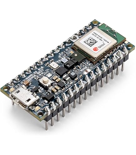
Before touching your goggles, gather these exact components to avoid mid-project frustration. You need two Arduino Nano 33 BLE boards—one mounts inside the goggles, the other in your transmitter. Never substitute standard Nano boards; the BLE module is essential for wireless communication. Source a micro-USB to USB-C cable (the Nano 33 BLE uses USB-C) for firmware uploads. Your DJI Goggles must be V1, V2, or Goggles 2/3 for Avata—older models lack compatible power points. Download the HeadTracker firmware from dlktdr’s GitHub repository before starting. Missing this causes delays when you’re mid-soldering.
Critical Hardware Connections to Avoid Damage
Connect power only from the goggles’ internal 5V rail—not the USB port. Locate the barrel connector’s solder points inside the case: the outer ring is ground, inner pin is 5V. Solder 28-gauge silicone wires (not stiff jumper wires) to these points. Use red for 5V, black for ground. Route wires away from moving parts like the focus dial. For the transmitter side, tap the trainer port’s signal, 5V, and GND pins—not the main power bus. Incorrect connections here can fry your radio’s receiver module. Always wrap solder joints in heat-shrink tubing, never electrical tape, which degrades with vibration.
Must-Have Tools for Safe Goggle Modification
Skip standard screwdrivers—use precision JIS #00 drivers to avoid stripping DJI’s tamper-proof screws. A 60W temperature-controlled soldering iron with a fine tip prevents cold joints on the Nano’s tiny pads. Third-hand tool with magnifying glass is non-negotiable for seeing the trainer port pins. Most critical: multimeter set to continuity mode. Test every connection before powering on. One short circuit can permanently damage your goggles’ mainboard.
Wiring Your DJI Goggles for Head Tracking: Step-by-Step

Mounting the Arduino Nano 33 BLE Inside Goggles
Open your DJI Goggles case using the JIS #00 driver—start from the top hinge to avoid cracking plastic clips. Locate the barrel connector near the battery compartment. Solder your 5V (red) and GND (black) wires directly to its solder pads. Route wires along the frame’s edge using double-sided foam tape—never zip ties that strain connections. Mount the Arduino on the inner plastic frame away from the display ribbon cable. Secure it with non-conductive epoxy putty, not hot glue which insulates poorly. Connect the centering button’s leads to Arduino pin A0 and GND. Test fit the goggles before final assembly—vibrations will loosen loose boards mid-flight.
Transmitter Trainer Port Wiring Without Bricking Your Radio
Disassemble your transmitter (FrSky, Radiomaster, etc.) to expose the trainer port PCB. Identify pins: SIGNAL (center), 5V (top), GND (bottom). Solder wires to these only after disconnecting the battery. Connect SIGNAL to Arduino pin D3, 5V to VIN, GND to GND on the second Nano. Never power the Arduino from transmitter battery voltage directly—use a 5V regulator if your radio outputs >5.5V. Route wires through unused cable channels inside the transmitter case. Secure the Arduino near the antenna module for optimal BLE range. Power-cycle your radio before testing head tracking—residual voltage can corrupt the Nano.
Flashing HeadTracker Firmware: Avoid Common Upload Failures
Configuring Arduino IDE for Nano 33 BLE
Install the Arduino Nano Boards 1.0.4+ core via Boards Manager—older versions cause BLE pairing failures. In File > Preferences, add this URL to “Additional Boards Manager URLs”: https://dl.espressif.com/dl/package_esp32_index.json. Select “Arduino Nano 33 BLE” under Tools > Board. Set “Optimize: Debug” to prevent memory overflow errors. Install the IMU Library (I2Cdev and MPU6050) through Library Manager. If the IDE shows “avrdude: stk500_recv(): programmer is not responding,” press the Nano’s reset button during upload.
Correct Firmware Upload Sequence
Flash the goggles-side Nano first using the HeadTracker_Goggles sketch. Verify IMU initialization completes by checking the Serial Monitor for “MPU6050 connection successful.” Then flash the transmitter-side Nano with HeadTracker_Transmitter. Incorrect sequence causes BLE connection timeouts. After uploading, disable Auto-Reset in Arduino IDE (Tools > Programmer > AVRISP mkII) to prevent accidental resets during flight. Test BLE pairing before reinstalling goggles—use your phone’s Bluetooth settings to find “HeadTracker” device.
Calibrate DJI Goggles Head Tracking in 5 Minutes
Execute the 6-Point Sensor Calibration
Open the HeadTracker mobile app (iOS/Android) and pair with the goggles’ Arduino. Hold your goggles perfectly still during each step. The app prompts six orientations:
1. Display facing up (like reading a book)
2. Display facing down
3. Left side down (ear to shoulder)
4. Right side down
5. Front facing up (forehead to ceiling)
6. Front facing down (chin to floor)
Hold each position for 3 seconds until the app beeps. Mistake to avoid: Moving between positions—set goggles on a non-metal surface between steps. Magnetic interference from phones or screws ruins magnetometer calibration.
Tune PPM Output for Smooth Camera Movement
In the app’s Output Settings, set PPM Frame Length to 22ms (standard for most radios). Map channels: CH1 = Pan (yaw), CH2 = Tilt (pitch). Start with Sensitivity at 50% and Deadband at 10%. Test by moving your head slowly left/right—the camera should pan smoothly without overshooting. If movements feel “jumpy,” increase Filter Smoothing to 70%. For cinematic shots, set Expo to 30% to reduce sensitivity at extreme head angles. Always save settings before closing the app—unsaved changes reset on reboot.
Integrate Head Tracking with Betaflight or EdgeTX
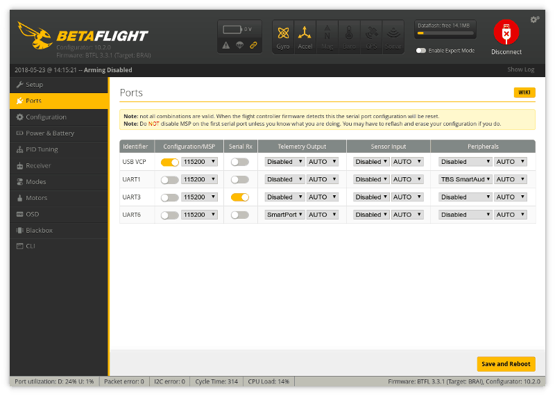
Configure Betaflight for MSP HeadTracker
In Betaflight Configurator, go to Configuration > Other Features. Enable “MSP HeadTracker” and set “Head Tracker Mode” to Relative. Under Receiver, set your head tracking channels (e.g., CH5 for pan, CH6 for tilt) as “AUX” channels. In Servo Mixer, assign pan/tilt channels to your gimbal servos. Set Min 1000, Max 2000, Mid 1500 to match PPM output. Critical step: Disable “Auto Center” in gimbal settings—head tracking requires manual centering via your physical button.
EdgeTX Channel Mapping for Instant Control
On your radio, go to Model Setup > Trainer. Set Mode to “PPM In” and Source to “Trainer Port”. In Mixer Setup, create new lines:
– Source: Trainer CH1 → Weight: 100% → Channel: Gimbal Pan
– Source: Trainer CH2 → Weight: 100% → Channel: Gimbal Tilt
Set Curve Type to “Custom” and apply a gentle S-curve for smoother motion. Test with “Simulator” mode—move your head while watching channel bars respond. If bars don’t move, check trainer port wiring polarity.
Fix Head Tracking Drift in 60 Seconds
Eliminate Gyro Drift During Hovering
Drift (camera creeping when head is still) means your magnetometer needs recalibration. Move 10 feet from metal objects—rebar in concrete or your transmitter causes interference. Open the HeadTracker app and select “Magnetometer Calibration.” Rotate goggles slowly in a figure-8 pattern for 20 seconds. Stop when the app shows “Calibration Successful.” If drift persists, reduce “Gyro Drift Compensation” to 0.05 in Advanced Settings—higher values overcorrect.
Stop Jittery Camera Movements Instantly
Jitter occurs when filtering is too low. In the app, increase “Filter Smoothing” to 85%—this dampens high-frequency noise from vibrations. If movements feel sluggish, raise “Update Rate” to 90Hz. For fixed-wing pilots, enable “Center Spring” with strength 30% to auto-center the view after glances. Never set smoothing above 95%—it introduces dangerous latency during aggressive maneuvers.
Set Landing Presets: Look Down Without Crashing
Program a physical button on your transmitter for instant ground view. In EdgeTX, go to Logical Switches > LSW1. Set Function to “Sticky”, Source to your button channel, Offset to 100%. In Mixer Setup, add a new line:
– Source: LSW1 → Weight: -30% → Channel: Tilt
This tilts the camera down 30% when pressed. Test over grass—press the button while landing to see the ground without pitching the aircraft down. For takeoff, create a second switch that tilts up +20% to clear obstacles.
Prevent Head Tracking Failures During Flight
Secure all wires with self-fusing silicone tape—it bonds to itself without residue. Before flying, press the centering button to reset neutral position—temperature changes cause drift. Check BLE signal strength in the HeadTracker app; replace transmitter batteries below 3.7V per cell. If connection drops, reduce “BLE Interval” to 7.5ms in firmware for stronger signal (increases power draw slightly). Always carry spare 5V wires—you can hot-swap a failed Arduino in 2 minutes mid-field.
Maintain Your DJI Head Tracking System Long-Term
Recalibrate sensors before every flying session—IMUs drift with temperature. Monthly, inspect solder joints with a magnifier for hairline cracks from vibration. Biannually, update HeadTracker firmware for latency improvements—newer versions cut lag to 12ms. When storing goggles, remove the centering button battery to prevent corrosion. For extended flights, add a 1000mAh LiPo inside the transmitter dedicated to the Arduino—prevents radio battery drain.
Head tracking transforms DJI Goggles from passive viewers into intuitive flight control systems. By following these precise wiring steps and calibration tricks, you’ll achieve sub-20ms latency with zero drift—critical for fixed-wing surveillance or cinematic drone shots. The Arduino Nano 33 BLE setup pays for itself the first time you spot an obstacle by glancing sideways instead of banking the aircraft. Now that your system is live, test it with gentle head movements in an open field before complex maneuvers. For deeper tuning, explore HeadTracker’s GitHub for advanced filter settings that match your flying style. Your next flight won’t just be seen—it’ll be felt.