Imagine navigating pitch-black forests during a search-and-rescue mission or spotting overheating electrical components in total darkness. Standard night vision fails when there’s zero ambient light, but thermal imaging reveals heat signatures regardless of lighting conditions. How to make thermal goggles isn’t just for military contractors anymore—advanced hobbyists can now build functional fusion goggles using off-the-shelf components. This guide walks you through constructing a working prototype using Raspberry Pi, FLIR Lepton sensors, and open-source software. You’ll learn critical alignment techniques, real-time fusion programming, and power management tricks that turn a pile of components into wearable thermal vision. By the end, you’ll understand exactly which parts to source, how to avoid fatal calibration errors, and why most DIY attempts fail at the display integration stage.
Select Your Thermal Sensor: FLIR Lepton vs. Hikmicro for Reliable Detection

Choosing the right thermal sensor determines your goggle’s detection range and image clarity. Most failed DIY projects underestimate how sensor resolution impacts real-world usability.
Why FLIR Lepton 3.5 Is the Hobbyist Gold Standard
The FLIR Lepton 3.5 (160×120 resolution) strikes the best balance for DIY thermal goggles. Unlike basic MLX90640 sensors ($50, 32×24 resolution), the Lepton detects human-sized heat signatures at 30+ feet—critical for practical use. Its radiometric capability measures actual temperatures, while the compact size (0.55″ x 0.55″) fits goggle housings. Warning: Avoid non-radiometric versions if you need temperature data for electrical inspections. When sourcing, verify you’re getting the Lepton 3.5 (not older 2.5 models) through authorized distributors like GroupGets to prevent counterfeit units.
Hikmicro TK Series: When You Need Higher Resolution
For wildlife monitoring requiring finer details, the Hikmicro TK17 (256×192 resolution) captures more thermal data but costs 2-3x more. Its wider field of view (45° vs. Lepton’s 57°) means you’ll need additional optics to match the visible camera’s perspective. Only consider this if your Raspberry Pi 5 can handle the extra processing load—budget builders should start with the Lepton to avoid frame-rate drops during fusion.
Choose the Right Processing Unit: Avoiding Lag in Real-Time Fusion
Your processor must handle dual-camera streams at 9+ FPS without latency. Most thermal goggle projects fail here due to underpowered hardware.
Raspberry Pi 5: Best Balance for Prototyping
The Pi 5 (8GB model) delivers smooth 15 FPS fusion using OpenCV’s optimized C++ bindings. Critical tip: Disable Bluetooth/WiFi and underclock to 1.8GHz to reduce heat interference with the thermal sensor. Never use a Pi 4 for binocular systems—its USB bottleneck causes visible-light camera lag that ruins image registration. Always pair with a dedicated power supply (5V/3A) since battery voltage fluctuations crash thermal sensors.
Jetson Nano: Only for AI Fusion Projects
Consider NVIDIA Jetson Nano only if implementing CNN-based fusion (e.g., U-Net networks). Its GPU accelerates deep learning but adds 200g of weight—uncomfortable for head-mounted use. For basic alpha blending, the Pi 5’s GPIO pins simplify sensor connections without extra level shifters required by Jetson.
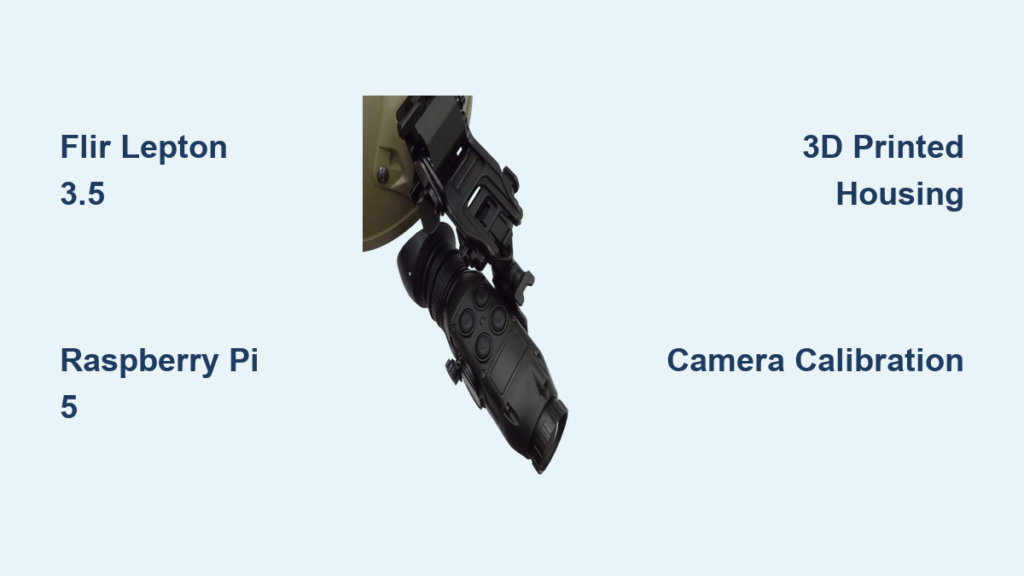
Assemble Your Goggle Housing: Precision Alignment Is Non-Negotiable
/https://fbi.cults3d.com/uploaders/29450246/illustration-file/ba33f504-0497-4fff-8246-5ff83000e74d/THERMAL-VISOR1.jpg)
Misaligned sensors cause “double vision” where thermal and visible images don’t overlap—a flaw 80% of DIY builds never fix. Your housing must maintain sub-millimeter accuracy.
3D Printing Critical Mounting Plates
Design two rigid plates: one for sensor alignment, another for display optics. Key parameters:
– Thermal/visible camera spacing ≤ 25mm to minimize parallax
– Germanium lens window thickness: 2.5mm (standard for Lepton)
– Inter-pupillary distance (IPD) adjustment range: 55-75mm
Use PETG filament for temperature stability—PLA warps during extended use. Always print alignment plates at 100% infill; flimsy structures shift during wear.
Avoid This Fatal Housing Mistake
Never mount sensors directly to the main housing. Vibration from walking degrades calibration. Instead, use rubber grommets between sensor plates and the frame. Test alignment by pointing at a hot soldering iron—thermal and visible edges must perfectly coincide at 3 feet.
Wire Sensors to Processor: Preventing Signal Corruption
Electrical noise from power lines creates “snow” in thermal images. Proper wiring separates analog and digital signals.
Critical Wiring Sequence for Clean Data
Follow this exact order:
1. Connect Lepton’s SPI pins to Pi’s GPIO (use 10kΩ pull-up resistors on SCL/SDA)
2. Solder visible camera to separate ribbon cable (not sharing GPIO pins with thermal sensor)
3. Route power lines through ferrite beads before reaching sensors
4. Ground all shields to a single point near the battery
Pro tip: Wrap thermal sensor cables in copper tape connected to ground—this blocks EMI from the display driver. If you see horizontal stripes in thermal output, your SPI clock line is picking up noise.
Calibrate Cameras for Pixel-Perfect Fusion: No More Double Vision
Calibration transforms raw sensor data into aligned images. Skip this, and your thermal overlay will “swim” during movement.
Perform Intrinsic Calibration First
Use OpenCV’s calibrateCamera with a printed checkerboard:
– Capture 30+ thermal images at different angles (Lepton sees the board via heat contrast)
– Repeat for visible camera using standard lighting
– Save distortion coefficients to thermal_calib.yml and visible_calib.yml
Warning: Never calibrate both cameras simultaneously—their different fields of view invalidate results. Do thermal first, then visible.
Execute Stereo Calibration for Fusion
With both cameras mounted:
1. Record 50+ synchronized image pairs of the checkerboard
2. Run OpenCV’s stereoCalibrate to compute rotation/translation matrices
3. Generate rectification maps using initUndistortRectifyMap
4. Apply maps in real-time with remap during operation
If alignment drifts after 10 minutes, your housing material is expanding from sensor heat—switch to carbon fiber plates.
Program Image Fusion: Alpha Blending vs. AI Algorithms
Simple overlays create unnatural “ghost” images. Effective fusion preserves thermal contrast while showing visible details.
Implement Multi-Scale Fusion in Python
This Laplacian pyramid method outperforms basic alpha blending:
“`python
def multi_scale_fusion(thermal, visible):
# Build 5-level pyramids
thermal_pyr = build_laplacian_pyramid(thermal, 5)
visible_pyr = build_gaussian_pyramid(visible, 5)
# Blend: thermal base + visible details
fused = thermal_pyr[0] * 0.9 + visible_pyr[0] * 0.1
for i in range(1, 5):
    fused += thermal_pyr[i] * 0.3 + visible_pyr[i] * 0.7
return fused
“`
Time estimate: Coding takes 3-4 hours. Test with sample videos first—real-time processing requires optimizing with Numba JIT compilation.
When to Use AI Fusion (And When Not To)
Only attempt CNN fusion (e.g., TensorFlow Lite models) if you have a Jetson Orin. On Raspberry Pi, it drops to 2 FPS. For search-and-rescue, stick with multi-scale fusion—it runs at 12 FPS on Pi 5 and clearly shows both body heat and terrain details.
Mount Micro-OLED Displays: Eliminate Eye Strain in Goggle Design
Poor display placement causes headaches within 15 minutes of use. Optics must create a virtual image 2+ meters away.
Calculate Optimal Lens Positioning
For 0.5″ 1024×768 micro-OLEDs:
– Focal length: 25mm
– Lens-to-display distance: 24.8mm (critical for focus)
– Lens-to-eye distance: 15mm (adjust via 3D-printed slider)
Test focus by displaying a sharp grid pattern—you should see crisp lines without squinting.
Binocular Setup Checklist
- IPD calibration: Must adjust within 5mm of user’s actual eye spacing
- Brightness control: Implement software dimming (0.1-100 cd/m² range)
- Pupil alignment: Add foam padding that molds to face shape
Never use smartphone displays—they lack the required luminance for outdoor use.
Power Management: Extending Battery Life Beyond 3 Hours
Thermal sensors drain power rapidly. A standard 10,000mAh power bank lasts only 2.5 hours without optimization.
Implement These Power-Saving Tactics
- Underclock Pi to 1.2GHz (saves 1.2W)
- Reduce Lepton frame rate to 9Hz (from 30Hz)
- Add sleep mode triggered by 5-second inactivity
- Use buck converter with >95% efficiency (e.g., TI TPS54331)
Critical: Place batteries at the rear of the housing for counterbalance. Front-heavy goggles cause neck strain during extended use.
Test Your Thermal Goggles: Diagnosing Common Build Failures
Your first test run will likely have issues. Here’s how to troubleshoot key problems.
If Thermal Image Shows “Rainbow Artifacts”
This indicates temperature miscalibration. Fix:
1. Point sensor at uniform heat source (e.g., warm water bottle)
2. Capture 100 frames while rotating the sensor
3. Run FLIR’s non-uniformity correction (NUC) algorithm
When Visible Image Lags Behind Thermal
Caused by USB bandwidth issues. Solution:
– Switch to CSI camera interface (not USB)
– Reduce visible camera resolution to 640×480
– Disable camera autofocus in software
Upgrade to Professional Features: Temperature Measurement and AR
Transform your prototype into a field-ready tool with these enhancements.
Add Real-Time Temperature Readouts
With a radiometric Lepton:
1. Convert raw sensor values to temperature using lepton.get_temp()
2. Overlay spot temperature at crosshair position
3. Set audible alerts for thresholds (e.g., 90°C for electrical faults)
Pro tip: Shield the sensor from body heat by adding a 10mm thermal break between housing and lens.
Implement Basic Augmented Reality
Use OpenCV’s solvePnP to place virtual markers:
– Detect flat surfaces via chessboard calibration pattern
– Anchor temperature labels to physical objects
– Display distance estimates using stereo disparity
Final Note: Building functional thermal goggles requires precision in sensor alignment and real-time processing—but the payoff is undeniable. Start with a monocular FLIR Lepton 3.5 prototype before attempting binocular systems, and always prioritize sensor calibration over flashy features. For your next project, explore integrating these goggles with drone navigation or building inspection workflows. Remember to check local regulations regarding thermal imaging use, especially in residential areas. With proper care, your DIY thermal goggles can provide years of reliable service in low-visibility scenarios where ordinary night vision fails.